
I went over to Polly Models at Long Eaton early this morning to pick up Kits 4 and 5 (motion and cylinders)
The kits were all ready for me and I had a brief chat with Lucy about my plans for building over the summer holiday period.
So what about Kit 4 which comprises the motion and buffers? As usual, I spent some time reading through the instructions and familiarising myself with the components. This is the first of the kits were it was not at all obvious what everything was and where it was supposed to go.
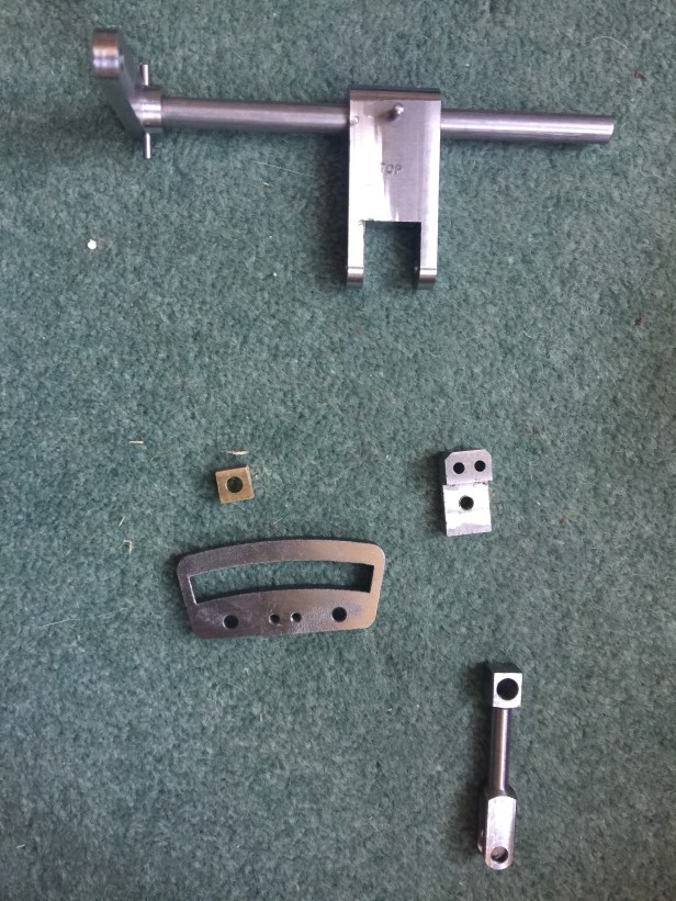
Below is a picture of the key elements of the motion: the weighshaft, the expansion link and die block and the trunion and bracket for connecting the motion to the weighshaft.
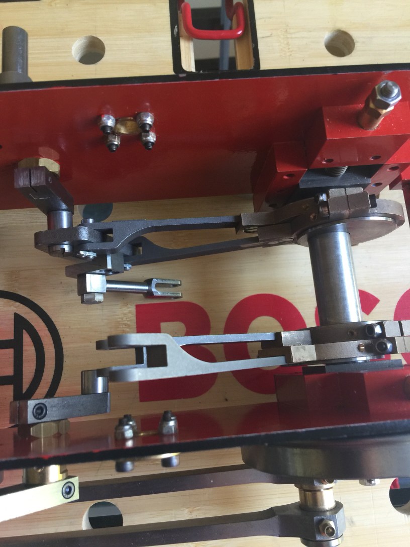
I got stuck in to the eccentrics and made good progress. Below you can see a photo of the rocker mechanism that will drive the valves. I didn’t take a separate photo of the rods and eccentrics which are also attached at the beginning of the process.
Once again Polly make things easy by letter stamping the straps on the eccentrics so that you can’t get them mixed up.
The key steps to the motion were:
- Fitting the eccentric straps and rods
- Filing the die block to fit the expansion link along its travel
- Assembling the rocker shafts and then fitting the expansion link mechanism
- Fitting the weighshaft and attaching it to the motion
Filing the die block was a bit of a fiddle as it needs to have concave and convex faces to fit the arc of the expansion link. You also have to file and emery cloth the inside surfaces of the expansion links to smooth the surface.
The other fiddle is fitting the split pins to the pins that hold the rods to the expansion link as these are quite tricky to get at as are the bolts that hold the die block to the rocker. Note to self: Get some new reading glasses as my varifocals aren’t up to the job.
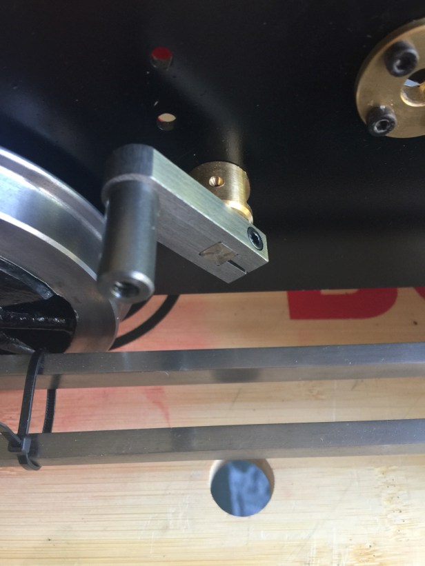
Below is the motion with just one of the expansion links fitted. There were some good pictures in the build instructions but I found myself referring to the Polly III drawings as well.
A key lesson from this part of the project was to test the fit of components before assembling on the locomotive. I had to take some bits to pieces several times to adjust the fit and then re-assemble.
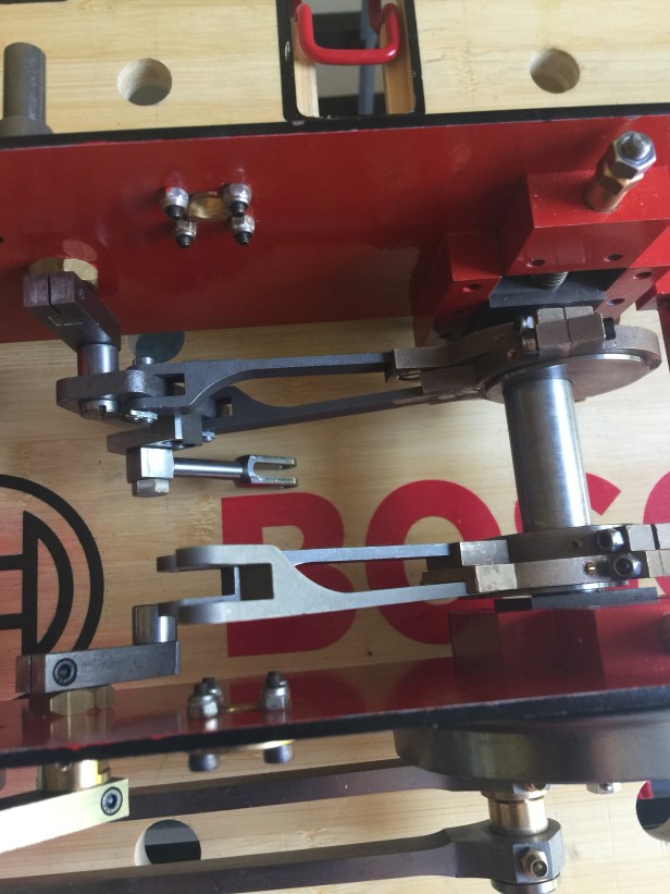
The final assembly of the motion now looks like this and it all seems to work quite smoothly. I need to be careful now that every time I have a little turn of things that there is plenty of oil on all the moving parts.
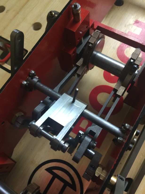
The eagle-eyed here will have spotted that, in this photo, I have managed to mount the weighshaft arm upside down (look at the picture at the start of this post to see the top clearly marked “top”). So today (5/7) I have taken a little of this to pieces and put it back together correctly
I hope to get on to the buffers at the weekend but I may take my time.
